Installing Cable Hardware for Bird Netting
One of the keys to a successful bird netting installation is how well the netting is fastened. The following guidelines will help you install your tensioned cable hardware.
NOTE: Each netting installation is different and some of the guidelines may not apply to your application. If you have questions or need help, please
Contact Nixalite.
A typical tensioned cable hardware installation follows these basic steps:
-
Install the corner hardware.
-
Install the cable guides.
-
Use connection hardware to fasten the cable to the corner hardware.
-
Thread the cable through the cable guides.
-
Fasten the cable to the turnbuckle eyelets. Then fasten the Turnbuckles to the corner hardware.
-
Install support cables if needed for interior support for the netting.
-
Attach the netting to cable system (covered on Install Bird Netting page).
-
Tension the cable (with the attached netting) by tightening the turnbuckles.
For an cable installation example, download the
Tensioned Cable Installation Example.
Installing Corner Hardware
 |
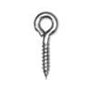
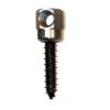
For Wood and Sheet Metal with Wood Core:
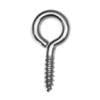
Screw Eye (part # Screw Eye L)
-
Drill a pilot hole for the screw eye, 1/8” diameter or less.
-
Thread the screw eye into pilot hole until the bottom of the eyelet touches the surface.
|
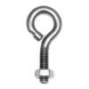 |
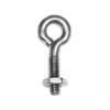
For Thick Steel:
Eyebolt with hex nut (part # Eyebolt w/nut L)
-
For steel up to ¾” thick: Drill a 9/32” hole through the steel. Insert the eyebolt stem through hole and thread on hex nut. Add washer if needed.
-
For steel more than ¾” thick: Drill a 13/64” hole at least 1-1/8” deep (or through). Tap drilled hole to ¼-20 NC, full depth. Insert eyebolts into threaded holes.
|
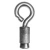 |
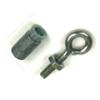
For Masonry:
Eyebolts with MS Anchors (part #s Eyebolt w/nut L, MS Anchor L).
-
Use Nixalite’s large machine screw anchor (1/2” x 1” drop-in anchor with 1/4-20 threads) to secure eyebolt in masonry surfaces.
-
Drill 1/2” diameter hole, 1” deep. Insert anchor and use supplied setting tool to properly seat anchor. Thread eyebolt into the anchor.
|
Installing Cable Guide Hardware
 |
For ALL Surfaces:
EZ-Clip (part # EZ-Clip).
-
All stainless steel EZ-Clips have a 3/16” mounting hole for all types of mounting hardware. Fastens to all surface materials with appropriate hardware.
|
 |
For Wood, Sheet Metal and Sheet Metal with Wood Core:
Small Screw Eyes (part # Screw Eye S).
-
Drill a pilot hole for the screw eye, 1/16” max or less (start with smaller drill).
-
Thread the small screw eye into pilot hole until the bottom of the eyelet touches the surface.
|
 |
For Steel and Iron:
Small Eyebolt with hex nut (part # Eyebolt w/nut S).
-
For steel up to 9/16” thick: Drill a 7/32” hole through the steel. Insert the eyebolt stem through hole and thread on hex nut. Add washer if needed.
-
For steel more than 9/16” thick: Drill a 9/64” hole at least 1” deep (or through). Tap each hole to 10-24 NC, full depth. Insert small eyebolts into threaded holes.
|
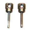 |
For Steel and Iron:
Sidewinder Cable Guides for Steel (part #s SWDR1.5, SWT1.5 and Sammy Socket).
-
All Sidewinders must be installed with the #14 socket driver (part# 14Sdriver).
-
SWDR1.5 for 1/4" thick steel. Self-drill, self-thread, no pilot required. Seat flush with socket driver.
-
SWT1.5 for 1/2" thick steel. Self-drill, self-thread, no pilot required. Seat flush with socket driver.
|
 |
For Masonry:
Small Eyebolt and Small MS Anchor (part #s Eyebolt w/nut L, MS Anchor S).
-
Use Nixalite’s small machine screw anchor (3/8” x 3/4” drop-in anchor with 10-24 threads).
-
Drill 3/8” diameter hole, 3/4” deep. Insert anchor and use supplied setting tool to properly seat anchor. Thread eyebolt into the anchor.
|
 |
For Masonry:
Sidewinder Cable Guide for Masonry: Sidewinders (part #s SWC-20 and 14Sdriver).
-
All Sidewinders must be installed with the #14 socket driver (part# 14Sdriver).
-
SWC-20 for masonry. Drill 1/4” diameter pilot hole, 1-1/2" deep. Seat flush with socket driver.
|
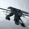 |
For Steel Flanges (I-beams, C-channel, Angle Iron, etc):
Flange Clips (part #s Fclip1/8, Fclip5/16, Fclip9/16).
-
Flange Clips are non-removable, hammer-on clips. DO NOT DRIVE FLANGE CLIPS ALL THE WAY ONTO THE FLANGE!
-
Leave 1/8” gap between the back of the clip and flange to pass the cable through.
-
TIP: Use a 1/8" thick piece of steel inside the clip as a 'stop'. Hammer the flange clip until it meets the 1/8" stop then remove the stop. An Allen Wrench works well.
|
Making Cable Loop Connections:
The following steps guide you through the process of creating simple loop connections. Use these steps to fasten the net cable to Corner Hardware and Turnbuckle Eyelets.
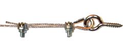
Connections with Wire Rope Clamps:
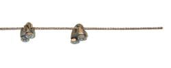 |
-
Push 1 thimble onto the eyelet of the eyebolt, screw eye or turnbuckle.
-
Slide 2 wire rope clamps over the end of the cable.
|
 |
-
Pass the cable through the eyelet (on the thimble) and then back through both clamps. Have at least 3” of lapped cable (the 'tag' end).
-
Position back clamp 2” from the eyelet and tighten ‘finger tight’. Position front clamp tight against the eyelet and tighten ‘finger-tight’.
|
 |
-
Take up cable slack by pushing the front clamp towards the eyelet while pulling on the tag end of the cable. Tighten all clamps.
|
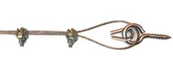
Connections with Ferrules:
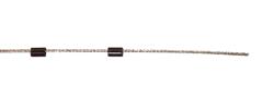 |
-
Push optional thimble onto the eyelet of the eyebolt, screw eye or turnbuckle.
-
Slide 2 ferrules over the end of the cable.
|
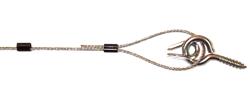 |
-
Pass the cable through the eyelet (using the thimble) and then back through both ferrules. Make sure there is at least 3” of lapped cable (the 'tag' end).
-
Take up cable slack by pushing the front ferrule towards the thimble while pulling on the tag end of the cable.
|
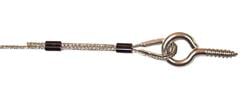 |
-
Crimp the front ferrule with the Ratcheting Crimp Tool (part # LOCO Lock).
-
Position the back ferrule 2” from the eyelet. Take up slack in cable and crimp ferrule in place.
|
Let Nixalite help you plan your netting installation!
Some of the steps covered here do not apply to all netting installations. Your installation may be different and require alternate procedures. If you have any questions, please
Contact Nixalite.